Buck Converter for Formula SAE
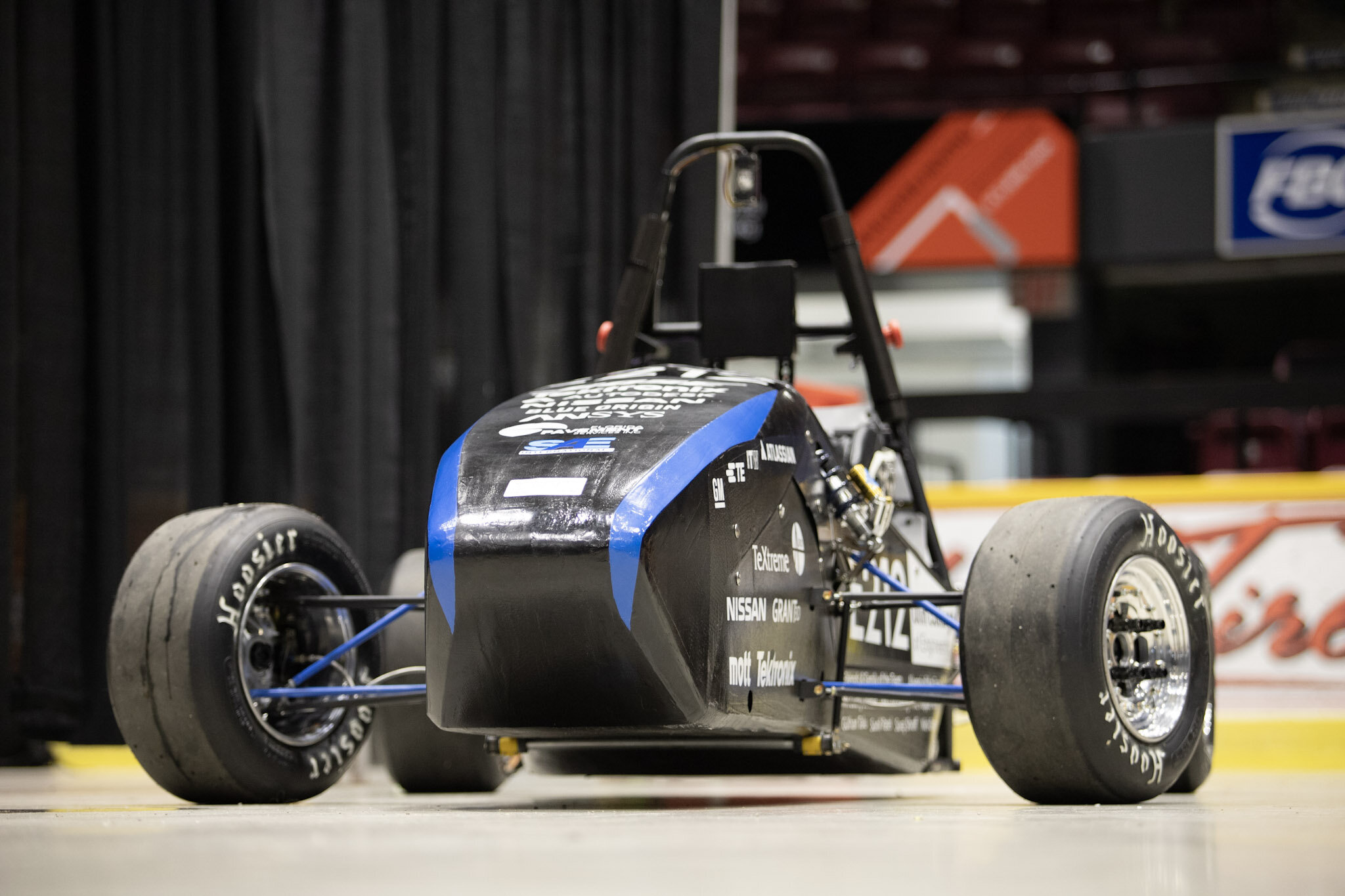
In this project, I mentored a first-year student, Sparsh, and together we developed a new buck converter circuit for Olin Electric Motorsports, my school’s FSAE team. Starting at scratch, we studied the fundamentals of power conversion and common topologies. We chose to go forward with a TI chip (TPS560430YF) as our buck converter and successfully designed a multi-subsystem custom circuit around it. We achieved Vpp < 30 mV in the worst-case scenario and Vpp < 2 mV in the best case scenario, with operational Vpp of ~8 mV.
Highlights
Think
Circuit analysis forms the fundamental of Electrical Engineering. In this case, I analyzed a simple buck converter model and then played with the variables to improve my understanding of this system.
Design
Once I understood the system, I spec’d parts according to the behavior I wanted. The image above shows the final schematic of the Buck converter circuit realized using a TI chip.
Create
Finally, this PCB layout was created. I populated it and tested it in the lab before deploying successfully it across the various subsystems in the FSAE car. I achieved Vpp < 30mV in the worst-case scenario and Vpp < 2mV in the best-case scenario.